Search within website

Case Study 2 - Electric motor

 Case Study 2 : Electric Motor

(For solution of the case study, click the link: Online case study 2 test. Solution will be declared after attempting online test)

Read the following and answer any four questions from 1 to 5.

 In 1821, Michael Faraday made the first electric motor. It worked using the force of magnetism. He created a simple electromagnet by taking a nail and a wire, wrapping about 100 loops of wire around the nail and connected it to a battery. With this, he had a simple electromagnet with north and south poles. In the middle of the nail, he had made a hole and put a spindle into the hole so that the nail could rotate. He then took a horseshoe-shaped magnet and placed the wire wrapped nail in the middle. He connected the wire of the north pole to the negative pole of the battery and the wire of the south pole to the positive pole. The basic law of magnetism told him what would happen: the north end of the electromagnet would repel the north end of the horseshoe-shaped magnet and would attract the south pole. The same happened on the other side of the nail, with the result that the nail turned. Faraday was not happy with the result of the electromotor, because the motor turned only once. He changed the polarity of the battery and the wire wrapped nail again turned just once. If he changed the polarity every time, when the north pole of the wire wrapped nail is opposite to the south pole of the horseshoe-shaped magnet, then he would have the result he was looking for. The wire-wrapped nail would turn and turn around the spindle (as long as the battery is not empty). 

                                                Design of simple electric motor


1. What type of energy conversion takes in an electric motor? 

(a) Electrical to mechanical 

(b) Mechanical to electrical 

(c) Mechanical to magnetic 

(d) Magnetic to electrical 


2.  On what principle does the working of the electric motor is based? 

(a) Fleming’s left hand rule 

(b) Electric current is induced in a coil when a magnet is moved closer or away from it. 

(c) A current carrying wire experiences a force in a magnetic field. 

(d) Magnetic field lines around a current carrying wire are concentric circles 


3. Faraday was not happy with his invention because his motor turned only once. What modification in his model would correct this defect? 

(a) Using a stronger horseshoe magnet 

(b) Using a high voltage battery 

(c) Using a split ring which can change the direction of current in the wire 

(d) Using nails was a bad idea as it is a magnetic material so using a non-magnetic material such as wood would correct this defect. 


 4. For maximum output of electric motor, What should be the angle between the direction of magnetic field and current carrying arms (AB and CD)?

 (a) 0° 

(b) 90° 

(c) 180° 

(d) it is independent of angle between magnetic field and current carrying arms 


5. In the figure shown with the passage, if arm AB of the coil experiences a force in a downward direction, then what would be the direction of the force on arm CD

 (a) downward 

(b) upward 

(c) same as the direction of the magnetic field 

(d) opposite to the direction of the magnetic field

Case Study 1 - Spherical mirrors

Case Study 1 - Spherical Mirrors

 Read the following passage and answer the questions that follows:

Anyone who has sat in the driver's or passenger's seat in a car has probably noticed the tiny wording, "Objects in mirror are closer than they appear," that runs along the bottom of the passenger-side rear view mirror. Some may question the logic of making objects seem like they are farther away than they actually are, but the reason is that such mirrors give the driver the best range of vision. Curved outwards spherical mirrors are commonly used as rear-view (wing) mirrors in vehicles because they give an erect, virtual, full size diminished image of distant objects with a wider field of view. These mirrors enable the driver to view a much larger area than would be possible with a plane mirror. 


Q1 Which type of mirror is used as a rear-view mirror in automobiles. 

(a) Plane mirror 

(b) Concave mirror 

(c) Convex mirror 

(d) Distorted mirror 


Q2  A bus of height 3m appears as a diminished image in the rear-view mirror of a car. The driver estimated the approximate image size of the bus to be just 3 cm in the mirror. What is the magnification produced by the mirror? 

(a) 1 

(b) 1/100 

(c) 100 

(d) 0.1 


Q3  The radius of curvature of the rear-view mirror is 400 cm. What is its focal length? 

(a) – 2m 

(b) – 400 cm 

(c) – 200 cm 

(d) 200 cm 


Q4 What is the advantage of using a curved-outwards spherical mirror as a rear view mirror? 

(a) it provides a shorter field of view. 

(b) it provides a much wider field of view 

(c) it provides a full size enlarged image 

(d) it provides a real image thus the driver is sure that the image is not fake.


Q5 The rear-view mirror of Sonali’s car was broken. In a hurry, she replaced the broken rear-view mirror with a concave mirror of the same size and focal length of 20 cm. What she would likely to observe in her mirror while driving? 

(a) She would observe no change because it has the same size as the previous one 

(b) She would observe an inverted image of traffic behind her car 

(c) She would observe an enlarged image of traffic behind her car 

(d) She would observe a virtual image of traffic behind her car


To know the answers of above questions, attempt the online test case study 1

Electric Current

 ELECTRIC CURRENT :

If electric charges such as electrons, ions, charged particles flows we say that there exist an electric current.

Consider a cell is connected to a torch bulb through metallic wires and a switch. On switching on the circuit, electric current is produced which flow through the wire and filament of the torch bulb, heat it up and the filament begins to glow.

Here in this case, electrons starts flowing when the cell was connected to the torch bulb through wires and switch. This flow of electrons in the metallic wire constitute the electric current.

Definition OF Electric Current: 
Electric current is defined as the rate of flow of charge flowing through a cross-section of a wire/conductor. 

Formula: 
If a net charge Q, flows across any cross-section of a conductor in time t, then the current I, through the cross-section is 

\[I = \frac{Q}{t}\]
SI Unit :
The SI unit of electric charge is coulomb (C) and time is second (s). Thus the SI unit of electric current is coulomb/second (C/s). This unit is given a special name called ampere (A), named after the French scientist, Andre-Marie Ampere (1775–1836). 

Definition of 1 ampere :

One ampere is that amount of current when an electric charge of one coulomb flows through a cross section of wire in one second. That is, 

\[1A=\frac{1C}{1s}\]
Small units of electric current: 
Small quantities of current are expressed in 
(i) milliampere

\[1mA=10^{-3}A\]
(ii) microampere

\[μA=10^{-6}A\]

Device used to measure current :
An instrument called ammeter measures electric current in a circuit. 

Symbol:

Connection in circuit: 
It is always connected in series in a circuit through which the current is to be measured. 

The Red terminal (positive terminal) is connected to the positive terminal of the battery and black terminal (negative terminal) is connected to the negative of the battery.

Direction of electric current :
Conventionally, in an electric circuit the direction of electric current is taken as opposite to the direction of the flow of electrons, which are negative charges. In an electric circuit electric current flows from the positive terminal of the cell to the negative terminal of the cell through the bulb and ammeter.


Electric circuit :
A continuous and closed path of an electric current is called an electric circuit.

Electric switch :
A switch makes a conducting link between the cell and the bulb. If the switch of the circuit is turned off, the current stops flowing and the bulb does not glow. 
Charge of an electron: 

\[1.6 \times 10^{-19}C\]
Number of electrons in 1C of charge: 

\[6.25 \times 10^{18}\]


NOW CHECK YOUR PROGRESS!!! 

1. What does an electric circuit mean? 
2. Define the unit of current. 
3. Calculate the number of electrons constituting one coulomb of charge. 
4. A current of 0.5 A is drawn by a filament of an electric bulb for 10 minutes. Find the amount of charge that flows through the circuit. 
5. Name the instrument used to measure electric current in a circuit. How is this instrument connected in a circuit? Draw a simple circuit diagram to explain your answer. 
6. Which particles constitute electric current in a metallic conductor? 
7. Name two units for expressing the small values of current. Also write their symbols. How are these units related to ampere? 
8. Write the use of following components in an electric circuit 
(a) Cell/battery 
(b) Ammeter 
(c) Connecting wires 
(d) Switch/plug key 

Why the colour of clear sky is blue?

Why the colour of clear sky is blue?


The atmosphere of earth is full of particles or molecules like N2, O2, O3, H2, H2O, dust particles etc. These are so small that we cannot see them with naked eyes. Even with powerful microscope of 100X or higher available in school labs, air particles are not visible (except dust particles). When sunlight encounters these particles there is a change in the direction of sun rays which lead to a phenomenon known as scattering of light.The sunlight consists of different frequencies from 430 – 770 THz (or wavelengths 390 -700 nanomoetres). The colour of the scattered light depends upon the size of the encountered particles. The process of selective scattering is known as Rayleigh scattering.


The size of the air particles has size comparable to the wavelength of visible light at the blue end. These particles are more suitable in scattering light of blue and violet colours as compared to red colour. This is the reason why sky appears blue in colour.

Due to pollution, large size particles are introduced in the atmosphere. These particles are efficient in scattering light of longer wavelengths also. This causes the pale blue or grey colour of the sky in a polluted atmosphere. 

Watch the video shown below on youtube. This video shows how a laser light is scattered by water and talcom powder. The scattering of laser by water or talcom powder makes its path visible (known as Tyndall's  effect) and this property can be used to study relection or refraction.


Uses of spherical mirrors

Uses of spherical mirrors 

Uses of Concave Mirror

1. A concave mirror is used as a reflector of light in headlights of automobiles to obtain a parallel beam of light. In a similar way concave mirrors are also used in torch lights and search lights.

In such a case, the source of light such as bulb is placed at the focus of the concave mirror. The light rays which fall on the concave mirror are reflected parallel to the principal axis and thus a parallel beam is obtained.

Practically, there are two bulbs one above the focus to obtain low beam (to light the ground nearby) and the other bulb slightly below the focus to obtain a high beam (to illuminate a larger distance but this will blind the driver approaching from opposite side).

In some reflectors the position of the bulb can be shifted slightly to obtain a low beam/high beam.


2. A concave mirror is used as a dentist’s mirror.
Dentists use a concave mirror to obtain the enlarged image of a tooth. The focal length of concave mirror used is large enough so that object (tooth) is placed between Focus and Pole. Thus a virtual, erect and magnified image of the tooth is obtained.

The position of object (tooth) is very important. Imagine what would happen if dentist view an inverted image using a concave mirror if it is placed between C and F. the image obtained will be magnified but inverted. In confusion, dentist may remove a healthy tooth.

3. Concave mirrors are used as concentrator of heat and light in solar furnace.
A solar furnace can be constructed by using a huge concave mirror or an array of plane mirrors mounted on a curved surface giving rise to a concave shape. The huge concave mirror is directed towards the sun. The sun’s rays get focused at F. At focus F, the temperature will be very high as all heat rays (infra red) get converged there. The temperature can reach up to 3500°C which can be used to melt metals.

One such solar furnace is installed in Mount Louis in France.

4. A concave mirror can be used as a shaving mirror.
Such a mirror will have a large focal length say 1m or 1.5m so that the person standing nearby would be placed between F and P. A virtual, erect and magnified image of the face is obtained which helps the person to see an enlarged image of his face while shaving.


Uses of Convex mirrors


1. It is used as a rear view mirror in automobiles.

Since a convex mirror provides a wider field of view and erect image of the object, it is a perfect choice for the rear view mirror.

The driver can view the wide view of traffic behind the vehicle.

The only disadvantage with the convex mirror is that the driver may be confused about the actual distance of the traffic behind his own vehicle. The image formed by the convex mirror is diminished and it gives an illusion that the object is very far. Even a closer object may appear very far in a convex mirror.

You can find this caution in every rear view mirror of automobile “Objects in the mirror are closer than they appear”.

2. Convex mirror are also used at the intersection of a busy traffic and at sharp curve.

Power of a lens

Power of a Lens

The power of a lens tell us its ability to converge or diverge a  beam of light falling on it.

Observe the following two convex lenses

The convex lens (A) with the short focal length converge the light rays by large angles and focus the rays close to the optical centre. Thus the lens with short focal length has a high converging power. 

The other lens (B) with longer focal length converge the light rays by small angle and focus the rays far from the optical centre. This lens with larger focal length has a low converging power.

Similarly for a concave lens, the shorter the focal length more is the diverging power of the lens.

Thus power of a lens may be defined as the reciprocal of its focal length in metres.

\[P=\frac{1}{f}\]
\[P=\frac{100}{f}\]  (if f is expressed in cm)

SI unit of power of a lens is dioptre. It is denoted by the symbol D.

Power of lens is said to be one dioptre if its focal length is 1m.

\[P=\frac{1}{f}\] 
\[P=\frac{1}{1}=1\]

Convex lens has a positive power as the focal length of convex lens is positive.

A concave lens has a negative power as the focal length of concave lens is negative.

Power of a combination of a lens

If lenses are combined then power of the combination is simply the algebraic sum of power of individual lenses.

Spherical lenses


Spherical Lenses
A spherical lens is a transparent medium bounded by two surfaces. Atleast one of the two surfaces must be spherical.
If the lens has one spherical surface then other surface will be plane. This results into two types of lenses.
(a) Plano convex lens
(b) Plano concave lens


If both the surfaces of the lens are spherical then following lens are obtained.
(c) Double convex lens ( or simply known as convex lens)

(d) Double concave lens ( or simply known as concave lens)

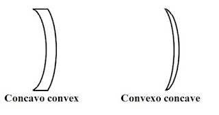
(e) Convexo concave
(f) Concavo convex 


Few terms related to spherical lens

Optical centre (O) : The centre of the lens is known as optical centre.

Principal axis :
The line passing through the centre of curvatures of spherical surfaces of lens and the optical centre is called principal axis.

Principal focus of a convex lens


When incident rays parallel to the principal axis falls on a convex lens then after refraction through the lens, all rays meet at a point on the other side of the lens. This point is known as the principal focus of a convex lens.

Since a lens is transparent light can enter the lens from either of the two surfaces. Hence a lens has two foci labeled as F1 and F2.


Focal length (f): The distance between optical centre and focus of a spherical lens is called focal length.

2F1 and 2F2 are the points located at twice the distance of focal length from the optical centre of the lens.

Principal focus of a concave lens

When incident rays parallel to the principal axis falls on a concave lens then after refraction through the lens, all rays diverge and appears to coming from a point on the principal axis. This point is known as the principal focus of a concave lens.

Since a lens is transparent light can enter the lens from either of the two surfaces of the concave lens. Hence a concave lens has two foci labeled as F1 and F2.


Watch a video for formation of image by a convex lens from our YouTube partner 'Learn n Hv Fun'.